Product Description
Type B Nylon Plastic Coupling Fluid Safety Irrigation Fluid Transfer Camlock Coupling
Body materials: fiber reinforced nylon
Handle: stainless steel
Gaskets:Buna-N (NBR), EPDM
The thread of camlock fittings are BSP,BSPT,NPT
SIZE:1/2″to 4″
Pressure :50-100 Psi( depending on size and temperature)
Operating temperature :-30-70°C (°C F 160)
When the temperature rises, the working pressure drops
Manufacture method:Injection molding
The use and connection way of cam and groove couplings: Type A camlock can usually be used with type D, type C, type B, type DC (Dust Cap) of the same size. To make a connection, simply slide the camlock adapter into the camlock coupling and with normal hand pressure, press the cam levers down.
Feature:
lightweight, convenient
l good wear resistance
l suitable for most chemicals, agricultural fertilizers
l economic utility
disconnect/connect without tools
Camlock fitting industry applications:
l industries: chemical, paint, agriculture, municipal, sewage
l applications: chemicals, solvents, varnishes, inks, fertilizers, wastewater
Body materials: fiber reinforced nylon
handle: stainless steel
Gaskets:Buna-N (NBR), EPDM
The thread of camlock fittings are BSP,BSPT,NPT
SIZE:1/2″to 4″
pressure :50-100 Psi( depending on size and temperature)
Operating temperature :-30-70°C (160°F)
When the temperature rises, the working pressure drops
l Manufacture method:Injection molding
Cam and groove couplings use and connection mode: Type C camlock can usually be used with type A, type E, type F, type DP (Dust Plug) of the same size. To make a connection, simply slide the camlock adapter into the camlock coupling and with normal hand pressure, press the cam levers down.
Feature:
lightweight, convenient
good wear resistance
suitable for most chemicals, agricultural fertilizers
economic utility
disconnect/connect without tools
Camlock fitting industry applications:
l industries: chemical, paint, agriculture, municipal, sewage
l applications: chemicals, solvents, varnishes, inks, fertilizers, wastewater
Nylon camlock coupling operating pressure:
| size | Working Pressure |
| 1/2″ – 2-1/2″ | 100 Psi |
| 3″ – 4″ | 50 Psi |
Our Advantage
We are experienced as we have been in this industry as a manufacturer for more than 10 years. Both of quality and service are highly guaranteed. Absolutely prompt delivery. We can produce according to specific drawings from customers. Welcome OEM/ODM project. Strict control on quality. High efficient and well trained sale service team. ISO9001, CE and SGS certified.
FAQ
1.Q: Are you a producer or trading company?
A: We are an experienced manufacturer. We own production line and kinds of machines.
2. Can you make our specific logo on the part?
Yes please provide me your logo and we will make your logo on the part.
3. Can you manufacture products according to my drawings?
Yes we can manufacturer according to client’s drawings if drawings or samples are available. We are experienced enough to make new tools.
4. Q: Can I get some samples?
A: We are honored to offer you our samples. Normally it is for free like 3-5 pcs. It is charged if the samples are more than 5 pcs. Clients bear the freight cost.
5. Q: How many days do you need to finish an order?
A: Normally it takes about 30 days to finish the order. It takes more time around CHINAMFG season, or if the order involves many kinds of different products.
6. what kind of rubber washer do you apply to camlock couplings?
Normally we use NBR gasket.
contact-info.html /* January 22, 2571 19:08:37 */!function(){function s(e,r){var a,o={};try{e&&e.split(“,”).forEach(function(e,t){e&&(a=e.match(/(.*?):(.*)$/))&&1
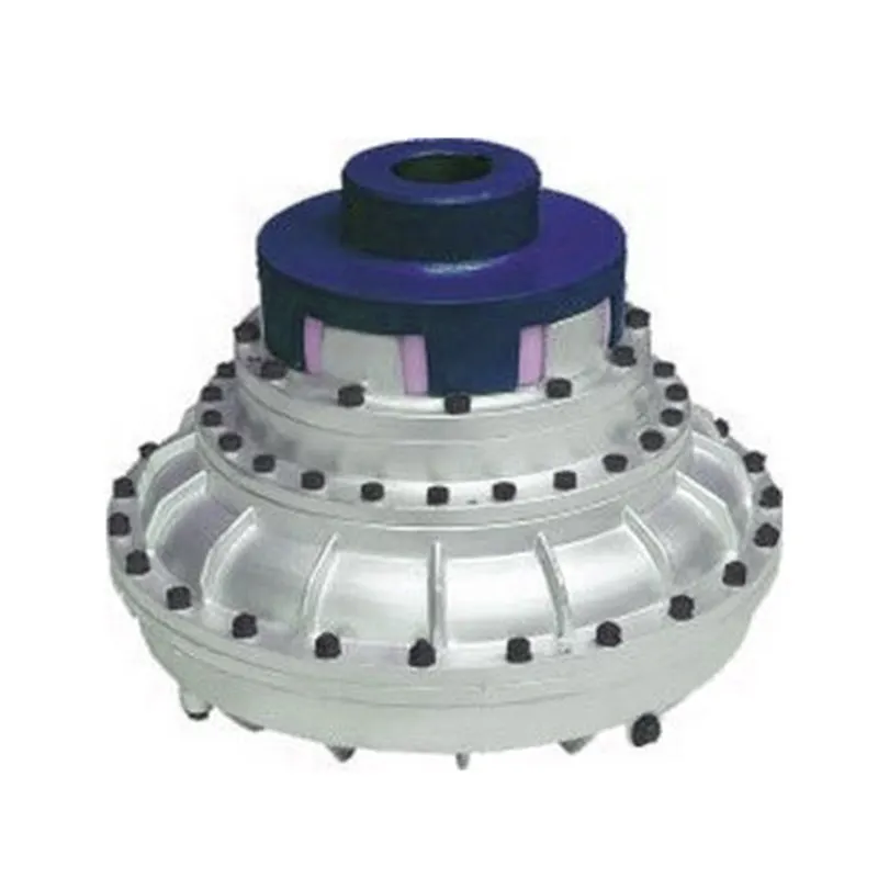
Fluid Coupling and Smooth Power Transmission during Starting and Stopping
A fluid coupling is designed to facilitate smooth power transmission during the starting and stopping phases of machinery and equipment. It achieves this by utilizing the principle of hydrodynamic torque transmission through a fluid medium.
Starting Phase: When power is initially supplied to the input shaft of the fluid coupling, the impeller (also known as the pump) begins to rotate, imparting energy to the fluid inside the coupling. As the fluid gains kinetic energy, it starts moving outward towards the turbine (also called the driven element) due to centrifugal force.
The kinetic energy of the moving fluid causes the turbine to start rotating, transmitting torque to the output shaft. During this starting phase, there is a slight time lag, known as the “slip,” between the impeller and the turbine. However, as the fluid coupling reaches its operational speed, the slip reduces, and the turbine matches the speed of the impeller, resulting in smooth power transmission from the input to the output shaft.
The fluid coupling’s ability to control the slip ensures a gradual and controlled acceleration of the driven equipment, minimizing stress on the drivetrain components and preventing sudden shock loads.
Stopping Phase: When power to the input shaft is reduced or cut off, the impeller slows down, and the kinetic energy in the fluid decreases. As a result, the fluid moves away from the turbine towards the center of the coupling, reducing the torque transmission between the input and output shafts.
This characteristic of the fluid coupling aids in smoothly decelerating the connected equipment, preventing sudden jolts or jerks during the stopping process. The ability to control the slip during deceleration ensures that the driven machinery comes to a gradual and controlled stop, enhancing safety and protecting the equipment from damage.
The combination of hydrodynamic torque transmission and the ability to control the slip makes fluid couplings ideal for applications where smooth power transmission during starting and stopping is essential. Industries such as mining, construction, metal processing, marine propulsion, and power generation benefit from the reliable and efficient performance of fluid couplings in various machinery and equipment.

Cost Implications of Using Fluid Couplings in Comparison to Other Power Transmission Methods
The cost implications of using fluid couplings in power transmission depend on various factors, including the application requirements, the size of the system, and the operational conditions. While fluid couplings offer several advantages, they may have different cost considerations compared to other power transmission methods like mechanical clutches, VFDs (Variable Frequency Drives), and direct mechanical drives.
1. Initial Investment:
The initial cost of a fluid coupling can be higher than that of a mechanical clutch or a direct mechanical drive. Fluid couplings contain precision components, including the impeller and turbine, which can impact their initial purchase price.
2. Maintenance Costs:
Fluid couplings are generally considered to have lower maintenance costs compared to mechanical clutches. Mechanical clutches have wear and tear components that may require more frequent replacements, leading to higher maintenance expenses over time.
3. Energy Efficiency:
Fluid couplings are highly efficient in power transmission, especially during soft-start applications. Their ability to reduce shock loads and provide a smooth acceleration can result in energy savings and operational cost reductions.
4. Space and Weight:
Fluid couplings are usually more compact and lighter than some mechanical clutches, which can be advantageous in applications with space constraints or weight limitations.
5. Specific Application Considerations:
The suitability and cost-effectiveness of fluid couplings versus other power transmission methods can vary based on specific application requirements. For example, in soft-start applications, fluid couplings may be the preferred choice due to their ability to reduce mechanical stress and protect connected equipment.
6. Lifespan and Reliability:
While the initial cost of a fluid coupling might be higher, their longevity and reliability can lead to lower overall life cycle costs compared to other power transmission methods.
In conclusion, the cost implications of using fluid couplings in power transmission depend on the particular application and the total cost of ownership over the equipment’s lifespan. Although fluid couplings may have a higher initial investment, their long-term reliability, energy efficiency, and lower maintenance costs can make them a cost-effective choice in many industrial applications.

Selecting the Right Size of Fluid Coupling for Your Application
To ensure optimal performance and efficiency, it’s essential to choose the right size of fluid coupling for a specific application. Here are the key steps in the selection process:
- Identify the Application Requirements: Understand the torque and power requirements of your application. Determine the maximum torque and power that the fluid coupling needs to transmit to meet the operational demands of the machinery or equipment.
- Check the Speed Range: Consider the speed range of your application. Ensure that the fluid coupling can operate effectively within the desired speed range, providing adequate torque transfer across the entire speed spectrum.
- Consider the Fluid Coupling Type: Choose the appropriate type of fluid coupling based on the specific needs of your application. Hydrodynamic fluid couplings are suitable for applications requiring smooth and gradual torque transmission, while constant-fill fluid couplings are more suitable for applications where some slip is acceptable.
- Calculate the Service Factor: Determine the service factor, which accounts for any additional loads or impacts the fluid coupling may experience during operation. Multiply the maximum torque requirement by the service factor to obtain the design torque.
- Refer to Manufacturer Data: Consult the manufacturer’s data sheets and specifications for various fluid coupling models. Compare the design torque with the torque capacity of different fluid coupling sizes to find the most suitable match for your application.
- Consider Safety Margins: It’s advisable to apply safety margins to ensure reliable operation. Select a fluid coupling with a torque capacity higher than the calculated design torque to account for potential variations in load or operating conditions.
- Verify Space Constraints: Ensure that the selected fluid coupling fits within the available space in your machinery or equipment, considering any installation restrictions or dimensional limitations.
By following these steps and carefully evaluating the requirements of your specific application, you can select the right size of fluid coupling that will deliver optimal performance, efficiency, and reliability.


editor by CX 2024-03-29
by
Tags:
Leave a Reply