Product Description
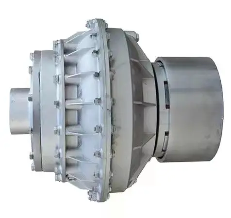
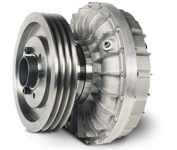
Four-axis precision CNC machining hydrodynamic fluid coupling
Muyang machinery is a manufacturer with the capability of comprehensive services of casting, forging, and machining, committed to the production of customized parts. Since established in 2002 (former Miaosen Machinery Co., Ltd), we’ve been supplying to the global market for over 15 years, serving industries including automotive, railway, gas and oil, medical machinery, construction machinery, gym equipment, etc.
|
Capability |
CNC machining center – MAX size: 600*1200*500mm General tolerance: ±0.005mm Machine qty: 6 sets CNC Milling – MAX size: 1200*500mm General tolerance: ±0.02mm Machine qty: 12 sets CNC turning – MAX size: φ0.5-φ800*1000mm General tolerance: ±0.005mm Machine qty: 35 sets |
|
Service: |
CNC turning, CNC milling, CNC grinding, CNC lathe machining, CNC boring, CNC drilling, CNC tapping, surface treatment, etc. |
|
Material available |
Stainless steel: SS201, SSS301, SS303, SS304, SS316, SS416, SS440C etc. Steel: Mild steel, Carbon steel, 4140, 4340, Q235, Q345B, 20#, 45# Brass/Bronze: HPb63, HPb62, HPb61, HPb59, H59, H68, H80, H90, C360, C260, C932 Copper: C11000, C12000, C36000 Aluminum: AL2017, AL2571, AL5052, AL5083, AL6061, AL6063, AL6082, AL7075 Iron: A36, 45#, 1213, 1214, 1215 Others per customers’ requirements |
|
Surface finish |
Aluminum alloy: Clear anodized, color anodized, sandblast anodized, hard anodized, brushing, polishing, powder coated, and painting Brass/copper/steel: Nickel plating, chrome plating Steel/Stainless steel: Zinc plating, oxide black, carburized, heat treatment, nitriding |
|
Measuring tools |
Micrometer, calipers, thread tools, high gauge, trapezoidal thread plug gauge, sclerometer, dial indicator, projector |
We promise our clients a careful, safe, and tight package for exporting!
Standard packing: pearl cotton/bubble bag + carton box + pallet/wooden box
Special packing: custom packaging + wooden box
FAQ:
1. Are you a manufacturer or trading company?
We’re a manufacturer with self-export rights.
2. What’s your main business?
Our main business is custom metal parts processed by CNC machining, casting, forging, etc., serving industries including railway, automobile, construction machinery, gym equipment, water gas, and oil.
3. Directly get to CONTACT or send your product drawing/inquiries to email, we will reply within 0.5 hours.
/* January 22, 2571 19:08:37 */!function(){function s(e,r){var a,o={};try{e&&e.split(“,”).forEach(function(e,t){e&&(a=e.match(/(.*?):(.*)$/))&&1
Fluid Couplings in Wind Turbines for Power Generation
Yes, fluid couplings can be used in wind turbines for power generation, and they play a significant role in optimizing the performance and efficiency of the turbine system. In a wind turbine, the fluid coupling is typically installed between the rotor hub and the main gearbox.
Here’s how fluid couplings are beneficial in wind turbines:
- Soft Start and Load Distribution: During the startup phase, the wind turbine experiences varying wind speeds, and a fluid coupling allows for a smooth soft start by gradually transferring torque from the rotor to the gearbox. This reduces mechanical stress on the components and prevents sudden load shocks.
- Torque Limiting: In high wind conditions, when the wind speed exceeds the rated limit, the fluid coupling can slip, decoupling the rotor from the gearbox. This torque limiting feature protects the gearbox and other drivetrain components from overloading and potential damage.
- Torsional Vibration Damping: Wind turbines are subject to dynamic loads and torsional vibrations due to wind gusts. The fluid coupling acts as a torsional damper, damping these vibrations and ensuring smoother and stable operation of the system.
- Overload Protection: If there is a sudden increase in wind speed, causing an overload condition, the fluid coupling helps absorb the excess torque and protects the turbine from overloading.
- Contamination Prevention: Wind turbine environments are often exposed to dust, dirt, and moisture. The fluid coupling provides an enclosed and sealed environment for the drivetrain, preventing contaminants from entering and extending the life of internal components.
- Redundancy: Some wind turbine designs employ multiple drivetrain stages, including redundant fluid couplings. This redundancy can enhance the reliability and safety of the turbine by providing backup systems in case of component failures.
- Energy Efficiency: By facilitating smooth start-ups and load distribution, fluid couplings contribute to the overall energy efficiency of the wind turbine system. This allows the turbine to harness wind energy more effectively and generate electricity efficiently.
Incorporating fluid couplings in wind turbines helps improve their overall performance, reliability, and lifespan while reducing maintenance requirements and operating costs. As a result, they are commonly used in modern wind turbine designs to optimize power generation from renewable wind resources.
Temperature Limitations of Fluid Couplings
Fluid couplings, like any mechanical component, have temperature limitations that must be considered to ensure their proper and safe operation. The temperature limitations of fluid couplings are influenced by the type of fluid used inside the coupling, the ambient operating conditions, and the specific design and construction of the coupling.
The primary concern regarding temperature is the heat generated during the operation of the fluid coupling. The heat is a result of friction and fluid shear within the coupling as it transmits power between the input and output shafts. Excessive heat generation can lead to the degradation of the fluid, affecting the performance and longevity of the coupling.
As a general guideline, most fluid couplings are designed to operate within a temperature range of -30°C to 80°C (-22°F to 176°F). However, the actual temperature limitations may vary depending on the manufacturer and the application requirements. For specific industrial applications where high-temperature environments are common, fluid couplings with higher temperature tolerances may be available.
It is crucial to consider the operating environment and the power demands of the machinery when selecting a fluid coupling. In applications with extreme temperatures, additional cooling mechanisms such as external cooling fins or cooling water circulation may be employed to maintain the fluid coupling within its safe operating temperature range.
Exceeding the recommended temperature limits can lead to premature wear, reduced efficiency, and even mechanical failure of the fluid coupling. Regular monitoring of the operating temperature and following the manufacturer’s guidelines for maintenance and fluid replacement can help ensure the longevity and reliability of the fluid coupling.
Always consult with the manufacturer or a qualified engineer to determine the specific temperature limitations and suitability of the fluid coupling for your particular application.

What is a Fluid Coupling and How Does It Work?
A fluid coupling is a type of hydraulic device used to transmit torque and power between two shafts without direct mechanical contact. It consists of three main components: the impeller, the turbine, and the housing. Fluid couplings are commonly used in various industrial applications, such as heavy machinery, conveyors, and automotive drivetrains.
Working Principle: The fluid coupling operates based on the principle of hydrodynamic power transmission. It uses a hydraulic fluid (usually oil) to transfer torque from the driving shaft (input) to the driven shaft (output).
1. Impeller: The impeller is mounted on the input shaft and is connected to the prime mover (e.g., an electric motor or an engine). When the prime mover rotates the impeller, it creates a swirling motion in the hydraulic fluid.
2. Turbine: The turbine is connected to the output shaft and is responsible for transmitting the torque to the driven system. The swirling motion of the hydraulic fluid generated by the impeller causes the turbine to rotate.
3. Fluid Filling: The area between the impeller and the turbine is filled with hydraulic fluid. As the impeller rotates, it creates a vortex in the fluid, which in turn causes the turbine to rotate.
4. Fluid Coupling Working: As the impeller and turbine are enclosed in the housing, the hydraulic fluid transfers rotational energy from the impeller to the turbine without any direct physical connection. The fluid coupling allows some slip between the impeller and the turbine, which enables smooth torque transmission, dampens shock loads, and provides overload protection.
5. Slip: Under normal operating conditions, there is a slight speed difference (slip) between the impeller and the turbine. This slip allows the fluid coupling to absorb shock loads and dampen vibrations, protecting the connected machinery from sudden jolts and overloads.
Fluid couplings are advantageous in applications where a gradual start-up and controlled acceleration are required. They provide a smoother and more flexible power transmission compared to direct mechanical couplings like gear couplings or belt drives.
However, it’s important to note that fluid couplings have some energy loss due to the slip, which can result in reduced efficiency compared to direct mechanical couplings like gear couplings or belt drives.


editor by CX 2024-03-27
by
Leave a Reply